Rtty interface (FSK/AFSK) with sound cards
Or how to remove the so called "ground loop"
and the reentry in the RTTY broadcast and make
radio and PC happily coexist
 One of the problems that affects our digital broadcasts
which make use of audio cards, as for instance RTTY and PSK 31,
is the reentry of the signal between RTX and the PC. These reentries
often block the keyboard, make it impossible to get back to RX, send
out "dirty" signals and so on.
One of the problems that affects our digital broadcasts
which make use of audio cards, as for instance RTTY and PSK 31,
is the reentry of the signal between RTX and the PC. These reentries
often block the keyboard, make it impossible to get back to RX, send
out "dirty" signals and so on.
A solution in these cases is to lower gradually the power,
until the problem is over; anyhow this is not the ultimate
solution, and in some cases you can put it into practice only
by getting down to few watts. To get rid of the problem efficiently and successfully, you should
isolate electrically both the RTX and the PC. Let’s see how:
The minimum kit in order to transmit digitally is the following:
- A cable connecting the audio output (headphones, aux, phone-patch...)
to the "line in" socket of the sound blaster
- A cable between the mike connector (or aux socket) and the "line out"
socket of the sound blaster "line-out"
 Both should be electrically interrupted by a small audio transformer,
like those used in the am/fm portable radio sets.
Both should be electrically interrupted by a small audio transformer,
like those used in the am/fm portable radio sets.
If you want to transmit by FSK and use the PTT operated via serial port,
you should use 2 more cables between the PC serial and RTX.
The home-site of the excellent software MMTTY (by JE3HHT) provides the
transistor based diagrams for the interface, which though do not isolate
radio and computer.
In this case the solution I have adopted to separate RTX/PC is to use 2
optocouplers instead of transistors:
- The first being used for the PTT commutation
- The second being used for FSK transmission (for the RTX that allow it)
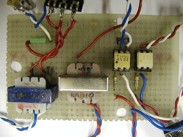
Here is the complete diagram of the interface I have realized for the TS940
with the precious contribution of Vincenzo IW3FOL and Vittorio I3VFJ.
CAUTION: Though the circuit works perfectly, I don't
take up any responsibility about the possible damages the diagram might cause
to the PC, radio or any other item.
This is the component's list:
AFSK (TX) side
- C1 - 100 nF Capacitor
- P1 - 4k7 ohm Potentiometer
- T1 - Audio transformer (1:1)
FSK (TX) side
- R2 - 560 Ohm 1/4 Watt Resistor
- OK2 - 4N32 Optocoupler
- LED2 - Led Diode
A/FSK (RX) + PTT side
- T2 - Audio transformer (1:1)
- R1 - 560 Ohm 1/4 Watt resistor
- OK1 - 4N32 Optocoupler
- LED1 - Led Diode
PIN's list
| diagram's Pin |
On generic radio |
On TS940 |
| A |
MIC |
PIN 1 (MIC) |
| B |
GND (MIC) |
PIN 7 (MIC) |
| C |
Radio data output |
PIN 3 (ACC2) |
| D |
PTT |
PIN 13 (ACC2) |
| E |
GND |
PIN 4+12 (ACC2) |
| F |
FSK/RTTY |
(RTTY) |
| G |
FSK/RTTY |
(RTTY) |
| diagram's Pin |
On PC (sound card) |
| H |
Line Out |
| I |
Line Out |
| J |
Line In |
| K |
Line In |
| diagram's Pin |
On PC (COM DB9) |
| L |
PIN 7 (RTS) |
| M |
PIN 5 (GND) |
| N |
PIN 3 (TXD) |
NOTICE: The circuit described here works perfectly
on Kenwood TS940, whose transmission circuit FSK is reverse operated compared to the
majority of other RTX:
for use with other radio sets you will have to slightly modify (only for the FSK (TX) part)
the circuit by connecting the OK2’s pin 1 (including R2 and LED2) to the "N" contact
instead of the "M" contact (see diagram) and the pin 2 to the "M" contact of PC’s COM port.
|